
If separate power supplies are used, it’s important to avoid placing the power jumper on the shield. The power supply can be provided through Arduino’s USB port, its DC jack, or from the shield’s 2-pin EXT-PWR block. If sharing a common power supply, a power jumper must be placed on the shield.

The power supply: The power supply to the shield can be used for both the shield and Arduino or the two can use separate power supplies. It’s used to extend four Arduino GPIO (or another microcontroller) to eight direction control pins for two of the L293D motor driver ICs.
L293d motor driver circuit diagram with ar serial#
The shift register: The 74HC595 is an 8-bit serial input and serial/parallel output shift register. The IC consists of two H-bridge to control the motors, each delivering p to 0.6A to a motor. This is ideal for two and four-wheel robot platforms. As there are two L293D ICs on the shield, it’s technically capable of controlling a total of four DC motors.

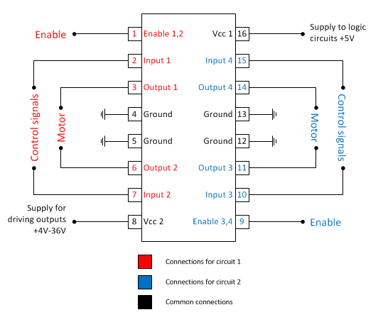
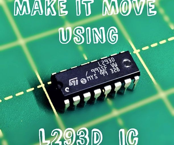
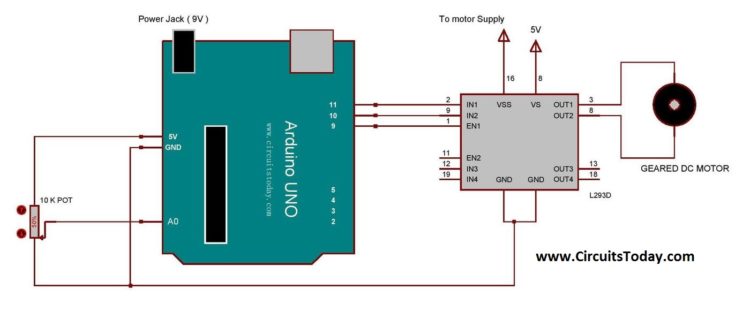
The motor driver: The L293D is a dual-channel H-bridge motor driver that can control two DC motors or a stepper motor at one time. The shield has several important components. The L293D motor driver shield includes two L293 motor driver ICs and a 74HC595 shift register IC. The full-featured L293D motor driver shield can control up to four bi-directional DC motors with 8-bit speed selection, two stepper motors, and two servo motors. One of the most popular motor driver shields used with Arduino is the L293D. These shields or ICs isolate a motor’s power supply and use control logic from the microcontroller circuitry. This is because of their higher current and power ratings, so motor shields or driver ICs are used instead. However, these motors typically cannot be driven directly by Arduino or another microcontroller. The most common types used for robotic applications include DC, servo, and stepper motors. The Arduino L293D motor driver shield guide is a robobtics project that involves driving various types of motors.


 0 kommentar(er)
